
Network bandwidth demands are accelerating faster than most organizations anticipated. As cloud services, virtualization, and data-intensive applications consume more resources, the pressure on data center infrastructure intensifies. Meeting data center cabling standards for 40 Gigabit and 100 Gigabit Ethernet is no longer a future consideration. It is an immediate requirement for organizations that want to avoid bottlenecks, maintain competitive performance, and support emerging technologies like artificial intelligence and real-time analytics.
The transition from 10G to 40G/100G Ethernet represents more than a simple speed upgrade. It demands careful planning around cable types, connector standards, distance limitations, and structured pathways. Organizations that approach this upgrade reactively often face costly rework, extended downtime, and performance issues that undermine the investment. Strategic planning based on current data center cabling standards ensures your infrastructure supports both immediate needs and future expansion.
Why 40G/100G Ethernet Matters Now
The shift to higher-speed Ethernet is driven by several converging factors. Server virtualization has increased the number of virtual machines per physical host, creating east-west traffic patterns that stress traditional network architectures. Storage area networks (SANs) require massive throughput for backup operations and disaster recovery replication. Video surveillance, IoT data streams, and hybrid cloud connectivity all contribute to bandwidth consumption that 10G infrastructure cannot sustainably handle.
Industry data shows that the average data center experiences 25-35% annual growth in bandwidth requirements. Organizations running at 60-70% of 10G capacity today will hit saturation within 18-24 months. At that point, upgrading becomes an emergency rather than a planned migration, resulting in rushed decisions and compromised implementations.
Forward-thinking IT leaders recognize that infrastructure upgrades require 12-18 months of planning and phased execution. Starting the process now positions your organization ahead of demand rather than scrambling to catch up.
Understanding Current Data Center Cabling Standards
Modern data center cabling standards are defined primarily by two organizations: the Telecommunications Industry Association (TIA) and the International Organization for Standardization (ISO). These standards specify cable performance characteristics, testing requirements, and installation practices that ensure reliable high-speed connectivity.
Key Standards for 40G/100G:
TIA-942: Addresses data center telecommunications infrastructure, including pathway design, cable types, and redundancy requirements. This standard provides the framework for planning structured cabling systems that support current and future speeds.
ISO/IEC 11801: International standard for structured cabling in commercial buildings and data centers. Defines performance categories for copper and fiber systems.
IEEE 802.3ba: Technical specification for 40 Gigabit and 100 Gigabit Ethernet, including supported cable types, distances, and physical layer requirements.
Compliance with these standards is not merely a best practice. It affects warranty coverage, insurance requirements, and resale value of your facility. Certified data center installation ensures your infrastructure meets industry benchmarks and performs as designed.
Fiber Optic Cable Types: Making the Right Choice
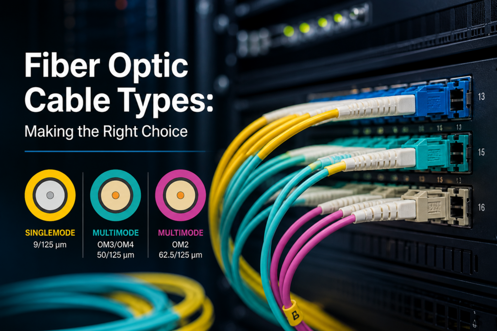
The foundation of any 40G/100G upgrade is selecting appropriate fiber optic cable. Two primary categories dominate data center deployments: multimode fiber (MMF) and single-mode fiber (SMF). Understanding the capabilities and limitations of each is critical to making cost-effective decisions.
Multimode Fiber Options
OM3 Fiber (50/125 micron):
- Supports 40G up to 100 meters
- Supports 100G up to 70 meters
- Suitable for short runs within racks or adjacent rows
- Lower cost than OM4 or OM5
OM4 Fiber (50/125 micron):
- Supports 40G up to 150 meters
- Supports 100G up to 150 meters
- Recommended for most intra-building connections
- Industry standard for new multimode installations
OM5 Fiber (50/125 micron):
- Optimized for shortwave wavelength division multiplexing (SWDM)
- Supports 40G/100G at same distances as OM4
- Future-proofed for 200G/400G applications
- Higher initial cost with long-term value
Single-Mode Fiber
OS2 Single-Mode Fiber (9/125 micron):
- Supports 40G/100G up to 10 kilometers (and beyond with appropriate optics)
- Required for campus backbone connections
- Essential for metro area network extensions
- Higher transceiver costs but unlimited distance scalability
For most data center environments, OM4 multimode fiber provides the optimal balance of performance, cost, and future-readiness. However, any connection exceeding 150 meters or requiring inter-building links should utilize OS2 single-mode fiber. Professional fiber optic installation ensures proper termination, testing, and documentation of your fiber infrastructure.
Connector and Transceiver Considerations
Cable type is only one component of the equation. Connectors and transceivers must match both the cable infrastructure and the active equipment specifications.
Common Connector Types:
MPO/MTP Connectors: Multi-fiber push-on connectors that support 12 or 24 fibers in a single interface. Essential for 40G/100G parallel optics solutions. These connectors enable high-density installations but require specialized cleaning and inspection procedures.
LC Duplex Connectors: Traditional two-fiber connectors still used in many 40G applications, particularly with BiDi (bidirectional) transceivers that send and receive on the same fiber pair.
Transceiver Standards:
QSFP+ (40G): Quad Small Form-factor Pluggable modules supporting 40 Gigabit Ethernet. Available in SR4 (short reach multimode) and LR4 (long reach single-mode) variants.
QSFP28 (100G): Evolution of QSFP+ for 100 Gigabit applications. SR4 modules support 100 meters on OM4, while LR4 modules reach 10 kilometers on single-mode.
Compatibility between transceivers and infrastructure is non-negotiable. An OM3 cable plant cannot support QSFP28 SR4 modules at full distance specifications. Mismatched components result in link errors, packet loss, and unreliable performance that is difficult to troubleshoot.
Migration Strategies: Minimizing Disruption
Upgrading data center cabling while maintaining operational continuity requires phased implementation strategies that balance risk, budget, and business requirements.
Parallel Infrastructure Approach
This strategy involves installing new 40G/100G infrastructure alongside existing 10G systems, then migrating workloads incrementally. Advantages include zero-downtime cutover and the ability to validate new infrastructure before decommissioning legacy systems. The primary drawback is higher initial capital expenditure and increased space consumption during the transition period.
Overlay Architecture
Overlay approaches use existing cable pathways but replace cable and terminations with higher-grade components. This works well when current pathways are properly designed but cable performance is the limiting factor. Requires careful coordination to avoid service interruptions during physical replacement activities.
Greenfield Deployment
New technology build-outs or major renovations provide opportunities to implement optimal designs without legacy constraints. This scenario allows deployment of structured cabling systems that support 40G/100G today while accommodating 200G/400G in the future.
Regardless of approach, professional planning identifies dependencies, critical paths, and rollback procedures that protect business continuity throughout the upgrade process.
Testing and Certification Requirements
Installing cables is only half the battle. Validation through comprehensive testing ensures your infrastructure performs according to data center cabling standards and supports rated speeds without errors.
Tier 1 Certification (Basic Continuity): Tests for proper connections and identifies opens, shorts, or reversals. Insufficient for validating 40G/100G performance but useful for initial installation verification.
Tier 2 Certification (Field Testing): Measures insertion loss and return loss across the entire link. Validates that the installed cable plant meets manufacturer and standards-body specifications for the intended application. This level is minimum acceptable for production data center deployments.
OTDR Testing (Optical Time Domain Reflectometry): Provides detailed analysis of fiber characteristics, including loss at each connection point, overall link loss, and identification of faults or anomalies. Essential for troubleshooting and long-term documentation.
All testing should be performed by certified technicians using calibrated equipment. Test results must be documented and retained for warranty validation and future troubleshooting. Proper structured network cabling implementations include comprehensive testing as a standard deliverable, not an optional add-on.
Power and Cooling Considerations
Higher-speed networking equipment generates more heat and consumes more power than previous generations. A fully populated 40G/100G switch can draw 500-800 watts compared to 200-300 watts for equivalent 10G hardware.
Upgrading network infrastructure without addressing power distribution and cooling capacity creates reliability risks and potential equipment failures. Planning should include:
- Power circuit capacity assessment
- UPS sizing and runtime calculations
- Hot aisle/cold aisle optimization
- Airflow management improvements
- Temperature and humidity monitoring
Integrated planning that addresses both data cabling and supporting infrastructure delivers better outcomes than treating these as separate projects. Coordination between networking, facilities, and electrical teams prevents costly oversights.
Common Pitfalls and How to Avoid Them
Even well-intentioned upgrades encounter predictable challenges. Awareness of common mistakes helps you avoid expensive rework:
Underestimating Cable Pathway Capacity: 40G/100G deployments often use trunk cables with 12-24 fibers. These cables have larger bend radius requirements and consume more pathway space than traditional cables. Inadequate pathways force suboptimal routing or require costly infrastructure modifications.
Neglecting Documentation: Undocumented cable plants become impossible to troubleshoot and maintain. Every fiber strand, patch panel port, and pathway route should be recorded in as-built drawings and cable management databases.
Skipping Pre-Installation Site Surveys: Assumptions about existing conditions lead to surprises during implementation. Professional site surveys identify obstacles, pathway limitations, and environmental factors before installation begins.
Mixing Cable Grades: Combining OM3 and OM4 fibers in the same link creates uncertainty about supported distances and applications. Standardizing on a single fiber grade throughout each project eliminates confusion and simplifies future expansion.
Budget Planning and ROI Considerations
Infrastructure upgrades represent significant capital investments. Typical costs for data center cabling upgrades include:
Fiber Cable and Terminations: $3,000 to $8,000 per rack depending on fiber count and distance
Structured Pathway Systems: $50 to $150 per linear foot for cable tray or conduit
Testing and Certification: $75 to $200 per terminated link
Labor and Project Management: 40-60% of total project cost
While these numbers may seem substantial, the cost of inadequate infrastructure is higher. Network bottlenecks reduce application performance, limit business capabilities, and create competitive disadvantages that are difficult to quantify but very real.
Organizations that proactively invest in infrastructure aligned with data center cabling standards position themselves for growth rather than constantly playing catch-up with capacity constraints.
Future-Proofing Your Investment
Technology evolution is inevitable. Smart infrastructure planning accommodates future requirements without complete replacement:
Install More Fiber Than Currently Needed: The cost difference between 12-fiber and 24-fiber trunk cables is minimal during initial installation but provides valuable expansion capacity.
Use Modular Connectivity: Cassette-based patch panels allow fiber type upgrades without replacing entire systems.
Document Everything: Comprehensive records enable efficient troubleshooting and informed decision-making for future upgrades.
Partner with Experienced Integrators: Vendors come and go, but relationships with skilled commercial electrical services providers ensure consistent quality and institutional knowledge that benefits long-term operations.
Taking Action: Your Path Forward
Upgrading to 40G/100G Ethernet readiness requires careful planning, expert execution, and adherence to established data center cabling standards. The complexity of modern data center infrastructure demands specialized knowledge that goes beyond basic IT skills. From selecting appropriate fiber types to implementing proper testing protocols, every decision impacts long-term performance and reliability.
Whether you are planning a complete data center overhaul or incrementally upgrading specific segments, professional guidance ensures your investment delivers maximum value. The right technology partner brings BICSI certification, hands-on experience with high-speed networks, and proven methodologies that transform technical requirements into operational excellence.
Contact Integrated Technology Solutions to discuss your data center cabling upgrade project. Our certified technicians specialize in fiber optic installation, testing, and certification that meets the highest industry standards. Let us help you build infrastructure that supports your organization’s growth and positions you for emerging technologies.
