
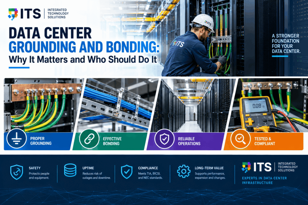
Most people planning a data center focus on servers, storage, networking, and cooling. Grounding and bonding rarely make the top of the list. That is a mistake.
Poor data center grounding and bonding is one of the most common causes of equipment damage, unexplained network errors, and personnel safety incidents in commercial facilities. It is also one of the most preventable. The standards are clear. The installation practices are well-established. The problem is that the work is often done by contractors who do not specialize in it, or skipped entirely because nobody assigned it.
This guide explains what data center grounding and bonding is, why it matters, what ANSI TIA 607 requires, and what to look for when choosing a contractor to do the work correctly.
What Is Data Center Grounding and Bonding?
Grounding and bonding are related but different concepts. Understanding the difference is important before you can evaluate whether a data center is properly protected.
Grounding
Grounding connects electrical equipment to the earth. The earth acts as a reference point for voltage. When equipment is properly grounded, fault currents have a safe path to dissipate rather than traveling through equipment, cables, or people.
In a data center, grounding protects servers, network equipment, storage arrays, and power distribution units from fault currents and transient voltage events. It also provides a stable voltage reference that helps sensitive electronics operate correctly.
Bonding
Bonding connects metal parts of equipment and infrastructure together so they share the same electrical potential. When metal enclosures, racks, cable trays, and conduit are all bonded together, there is no voltage difference between them. That matters because voltage differences between metal surfaces create current flow, which damages equipment and creates shock hazards.
Think of bonding as making sure everything metal in the room is “at the same level.” If two metal surfaces have different voltage levels, current flows between them whenever a conductor touches both. In a data center full of cables and equipment, that happens constantly.
Why Both Matter
Grounding without bonding leaves equipment at different voltage potentials even though each piece is connected to the earth. Bonding without grounding creates a unified system that has no safe path for fault current to dissipate. Data center grounding and bonding work together as a system. One without the other provides incomplete protection.
What Can Go Wrong Without Proper Data Center Grounding and Bonding
The consequences of inadequate data center grounding and bonding range from annoying to catastrophic. Here are the most common failure modes.
Equipment Damage from Transient Voltage Events
Lightning strikes, utility switching events, and load changes on the power grid produce voltage transients. These transients propagate through power and data cables into equipment. A properly grounded and bonded system gives those transients a low-impedance path to dissipate harmlessly. A system with inadequate grounding and bonding lets transients flow through sensitive circuit boards, causing immediate failures or cumulative damage that shortens equipment life.
Data centers in Texas are particularly exposed to this risk. The state sees significant lightning activity, and the commercial power grid experiences switching transients that are routine but damaging to unprotected equipment.
Electromagnetic Interference
Grounding and bonding also control electromagnetic interference, or EMI. When cables and equipment enclosures are not properly bonded, they act as antennas. They pick up and radiate electromagnetic noise that corrupts data signals and causes network errors that are difficult to diagnose.
Many unexplained network performance problems in data centers trace back to grounding and bonding deficiencies. Bit errors, packet loss, and intermittent connectivity issues that cannot be explained by software or hardware failures are often grounding problems in disguise.
Static Discharge
Electrostatic discharge, or ESD, is a direct threat to semiconductor devices. Static charges build up on people, equipment, and non-conductive surfaces. When a charged object comes close enough to a sensitive device, the charge discharges through the device. A single ESD event can destroy a circuit board instantly. Lower-energy events cause latent damage that shows up as premature failure weeks or months later.
Proper data center grounding and bonding gives static charges a controlled path to dissipate continuously, rather than accumulating until they discharge destructively.
Personnel Safety
Voltage differences between bonded surfaces create shock hazards. A technician touching two metal surfaces at different potentials simultaneously can receive a shock. In the worst cases, fault currents without proper grounding paths travel through the path of least resistance, which may be a person.
Data center grounding and bonding is a life safety requirement, not just an equipment protection measure. This is one reason the work needs to be done by qualified contractors, not improvised.
Compliance and Insurance Risk
Most data center equipment warranties require installation per applicable standards. ANSI TIA 607 grounding requirements are the baseline for commercial telecommunications and data center infrastructure. Insurance policies for commercial facilities often require compliance with applicable electrical and infrastructure standards. A facility with documented grounding and bonding deficiencies may face warranty claim denials and insurance complications after an incident.
ANSI TIA 607: The Grounding and Bonding Standard
ANSI TIA 607 is the primary industry standard for grounding and bonding in commercial telecommunications and data center environments. The current version, ANSI/TIA-607-C, covers telecommunications bonding and grounding (earthing) infrastructure for commercial buildings. Understanding what it requires is the starting point for any data center grounding and bonding project.
What ANSI TIA 607 Covers
ANSI TIA 607 grounding requirements apply to telecommunications rooms, entrance facilities, and data center environments. The standard defines the components, configurations, conductor sizing, and installation methods required for a compliant grounding and bonding infrastructure.
Key elements of ANSI TIA 607 grounding include:
• Telecommunications Main Grounding Busbar (TMGB). A dedicated copper busbar installed in the main telecommunications room or data center, connected directly to the building electrical ground. This is the central reference point for the entire grounding system.
• Telecommunications Grounding Busbar (TGB). Copper busbars installed in each telecommunications room or IDF, bonded back to the TMGB through the Telecommunications Bonding Backbone (TBB).
• Telecommunications Bonding Backbone (TBB). A bonding conductor that connects all TGBs back to the TMGB, creating a continuous low-impedance path throughout the facility.
• Equipment Bonding Conductors (EBC). Conductors that bond individual equipment racks, cable trays, and metallic infrastructure elements to the nearest grounding busbar.
• Conductor sizing. ANSI TIA 607 specifies minimum conductor sizes for each element of the system. Under-sized conductors increase impedance and reduce the effectiveness of the grounding system.
What ANSI TIA 607 Does Not Cover
ANSI TIA 607 grounding covers telecommunications and information technology infrastructure. It does not replace the electrical grounding requirements of the National Electrical Code (NEC) for power systems. A complete data center grounding and bonding program addresses both ANSI TIA 607 requirements for IT infrastructure and NEC requirements for electrical systems. The two sets of requirements are complementary. A facility that only addresses one has incomplete protection.
Why ANSI TIA 607 Compliance Matters
ANSI TIA 607 grounding provides a documented, testable standard for the grounding and bonding system. When an installation follows the standard, it can be tested and certified. The test results create a baseline record that supports future inspections, warranty claims, and insurance documentation.
A data center grounding and bonding installation that is not designed and documented to ANSI TIA 607 grounding requirements cannot be meaningfully tested or certified. If a problem occurs later, there is no baseline to compare against. And if the installation is audited, the absence of standards-based documentation is a red flag for regulators, insurers, and auditors.
Components of a Proper Data Center Grounding and Bonding System

A complete data center grounding and bonding installation covers several interconnected components. Each one contributes to the overall effectiveness of the system.
Main Grounding Busbar (TMGB)
The TMGB is the foundation of the grounding system. It is a solid copper busbar, typically 6mm thick and at least 100mm wide, installed in the main data center room or telecommunications space. It is connected to the building electrical ground with a conductor sized per ANSI TIA 607 requirements.
The TMGB needs to be accessible for inspection and testing. It should be labeled clearly and documented in the as-built records for the facility. Future technicians need to be able to find it and verify its integrity without guessing.
Grounding Busbars in Equipment Rooms (TGB)
Each IDF or secondary equipment room gets its own grounding busbar, the TGB. The TGB connects back to the TMGB through the bonding backbone conductor. Equipment in that room bonds to the local TGB rather than running long conductors back to the main busbar.
The TGB location matters. It should be close enough to the equipment it serves that bonding conductors can be kept short. Long bonding conductors have higher impedance and are less effective at equalizing potentials.
Bonding Backbone (TBB)
The bonding backbone connects all TGBs to the TMGB in a continuous conductor run. ANSI TIA 607 grounding specifies minimum conductor sizing for the TBB based on the length of the run. The TBB must be a single continuous conductor, not spliced.
The TBB is often installed in the same pathway as the fiber backbone, because both run between telecommunications rooms. Coordination between the cabling design and the grounding design at the start of the project avoids pathway conflicts and retrofit costs.
Equipment Rack Bonding
Individual equipment racks must be bonded to the grounding system. Each rack gets a bonding conductor connected from the rack frame to the nearest grounding busbar. The conductor must make a clean metal-to-metal connection, not through painted surfaces, which are insulators.
Rack bonding is one of the most commonly missed elements of data center grounding and bonding installations. Racks that are not bonded create islands of potentially different electrical potential in the middle of the equipment environment. Cables that pass between an unbonded rack and the broader infrastructure carry the voltage difference directly to equipment ports.
Cable Tray Bonding
Metal cable trays must be bonded to the grounding system. Cable trays carry data cables throughout the data center. If the tray is at a different potential than the equipment the cables connect to, the tray acts as a source of noise and a conduit for fault currents.
Cable tray bonding conductors connect the tray sections to the nearest grounding busbar. Tray sections connected with mechanical fasteners only are not reliably bonded, because the fasteners may not make a consistently low-impedance connection over time.
Raised Floor Bonding
Raised floor systems in data centers are typically metal-framed. Those frames must be bonded to the grounding system. Raised floor panels sit on metal pedestals. The entire structure needs to be treated as a metal surface that requires bonding, not just a structural element.
Raised floor bonding is particularly important in older data centers that are being upgraded. Original installations often addressed power and cooling but not telecommunications grounding. A grounding retrofit needs to address the raised floor system as part of the complete scope.
Testing and Certifying a Data Center Grounding and Bonding System
A grounding and bonding installation that is not tested and documented provides uncertain protection. You cannot tell by looking at it whether the conductors are properly sized, the connections are making good metal-to-metal contact, or the overall system is performing as designed. Testing answers those questions.
Ground Resistance Testing
Ground resistance testing measures the resistance of the grounding electrode system to the earth. Lower resistance is better. High ground resistance means fault currents cannot dissipate effectively. ANSI TIA 607 grounding does not specify a maximum ground resistance value for telecommunications grounding, but the electrical grounding system the TMGB connects to must meet NEC requirements. Fall-of-potential testing is the standard method for measuring ground resistance.
Bonding Conductor Resistance Testing
Bond resistance testing measures the resistance of the connections between equipment, busbars, and the backbone conductor. This test identifies connections that have high resistance due to loose hardware, painted surfaces, corrosion, or under-sized conductors. The test is typically performed with a low-resistance ohmmeter and should find values in the milliohm range for properly made connections.
Documentation
Test results need to be documented and included in the project closeout package. The documentation should include a diagram of the grounding and bonding system as installed, the conductor sizes and lengths, the busbar locations, and the test results for each connection and each ground electrode test. This package is the baseline that supports future inspections, warranty claims, and system additions.
A contractor who does not provide test documentation with a data center grounding and bonding installation has not completed the job. The documentation is part of the deliverable.
Who Should Do Data Center Grounding and Bonding Work
This is where many data center projects go wrong. Grounding and bonding work gets assigned to the lowest-cost bidder, treated as a finish item that can be done by whoever has time, or folded into the general electrical scope without specific expertise requirements.
Data center grounding and bonding requires a contractor who understands both the electrical and telecommunications aspects of the work. That is not every electrical contractor, and it is not every low voltage contractor. It is a specialty.
What to Look for in a Grounding and Bonding Contractor
When evaluating contractors for data center grounding and bonding work, look for these qualifications:
• Familiarity with ANSI TIA 607 grounding. The contractor should be able to explain what the standard requires and how their installation will meet it. If they cannot, they are not the right contractor for this work.
• Experience with TMGB and TGB installation. Ask for examples of past data center grounding and bonding projects. The contractor should be able to describe the busbar configuration, conductor sizing, and testing approach from projects they have completed.
• Testing capability. The contractor should have the test equipment and know how to use it. Ground resistance testing and bond resistance testing require specific instruments. A contractor who does not have them cannot certify their own work.
• Documentation delivery. Ask specifically what documentation they will provide at project closeout. The answer should include as-built drawings, conductor schedules, and test reports. A vague answer is a warning sign.
• Coordination with the electrical contractor. The telecommunications grounding system connects to the electrical grounding system. The two contractors need to coordinate on the connection point, conductor sizing, and testing. A low voltage contractor who has never worked alongside an electrical contractor on a grounding project may miss that interface.
Why a Specialized Low Voltage Contractor Is the Right Choice
Electrical contractors handle power system grounding every day. That expertise does not automatically extend to telecommunications grounding. The NEC governs power grounding. ANSI TIA 607 grounding governs telecommunications grounding. They are related but different, and the installation details differ as well.
A low voltage contractor who specializes in data center infrastructure understands both sides of the interface. They design the TMGB and TGB system, coordinate the connection to the electrical ground, install equipment rack bonding and cable tray bonding, test the complete system, and deliver documentation that covers the full telecommunications scope.
ITS provides data center infrastructure services including grounding and bonding installation for commercial data center environments in Texas and nationwide. Our data center grounding and bonding work follows ANSI TIA 607 grounding requirements. We install, test, and document every system to deliver a certified, compliant installation.
Common Mistakes in Data Center Grounding and Bonding
These are the errors ITS sees most often when auditing existing data center grounding and bonding systems.
Using the Wrong Conductor Size
ANSI TIA 607 grounding specifies minimum conductor sizes for the TBB, TGB bonding conductors, and equipment bonding conductors. Under-sized conductors are one of the most common deficiencies found in existing installations. The problem is not always visible, because a small conductor looks similar to a correctly sized one. Testing identifies it by measuring higher-than-expected resistance.
Bonding Through Painted Surfaces
Paint is an insulator. Bonding conductors that connect to equipment racks through painted surfaces may look correct but make no electrical connection at all. Proper bonding requires clean metal-to-metal contact. Where paint is present, it must be removed at the connection point or the connection must be made through an area of the rack that is not painted.
Omitting Rack Bonding
Equipment racks are often omitted from the bonding scope because they are not explicitly called out in the construction documents. The result is a data center where the busbars and backbone are correctly installed but individual racks are floating at whatever potential they happen to be at. This creates exactly the EMI and ESD exposure the system is supposed to prevent.
Not Testing After Installation
A grounding and bonding installation that has not been tested has not been verified. Connections that look correct may not make adequate electrical contact. Conductors that appear properly routed may have been damaged during installation. Testing is the only way to know the system performs as designed.
Leaving Out Documentation
An installation without documentation is difficult to maintain, nearly impossible to audit, and provides no baseline for future work. Every data center grounding and bonding installation should produce a documented as-built record that the owner can use and the next contractor can build on.
Data Center Grounding and Bonding for New Construction vs. Retrofit
The approach differs depending on whether you are building a new data center or retrofitting an existing one.
New Construction
New construction is the easiest time to install data center grounding and bonding correctly. The infrastructure is accessible. The electrical ground is being established at the same time. Coordination between trades is built into the construction schedule.
For new construction projects, grounding and bonding should be part of the low voltage scope from the start, alongside structured cabling and data center infrastructure. Treating it as a separate afterthought creates coordination problems and often results in work that has to be redone when it does not meet the electrical contractor’s requirements at connection.
Retrofit
Retrofitting grounding and bonding into an existing data center is more complex. Equipment may need to be moved temporarily to access rack frames and cable trays. Work has to be scheduled around operational requirements. The existing electrical ground needs to be located and evaluated before the TMGB connection can be designed.
A thorough site assessment before the design is developed is essential for a retrofit project. The assessment identifies the existing ground electrode location, evaluates the available pathway for the bonding backbone, inventories the rack and cable tray infrastructure that needs bonding, and identifies any conditions that will affect the installation approach.
ITS conducts site assessments for data center grounding and bonding retrofit projects as part of the project development process. We document existing conditions, design the grounding and bonding system to ANSI TIA 607 grounding requirements, and install the system with minimal disruption to ongoing data center operations.
How Data Center Grounding and Bonding Fits Into a Complete Data Center Infrastructure Project
Data center grounding and bonding does not exist in isolation. It is one component of a complete data center infrastructure program. When ITS delivers a data center project, grounding and bonding is included in the scope alongside structured cabling, rack installation, fiber backbone, and power distribution.
Treating grounding and bonding as a standalone item creates coordination problems. The bonding backbone runs in the same pathways as the cabling backbone. The TMGB installation requires coordination with the electrical contractor. Rack bonding happens at the same time as rack installation. When one contractor handles the full scope, these coordination points are internal rather than between separate companies.
For clients managing a broader commercial technology program, our technology build-out approach covers how to structure the delivery of a complete low voltage scope, including data center infrastructure, to minimize coordination gaps and maximize installation quality.
Frequently Asked Questions: Data Center Grounding and Bonding
Is data center grounding and bonding required by code?
Yes. The National Electrical Code (NEC) requires electrical grounding for power systems. ANSI TIA 607 grounding is the industry standard for telecommunications and IT infrastructure bonding and grounding. While ANSI TIA 607 is a voluntary standard rather than a code requirement in most jurisdictions, it is referenced in many building specifications and is required by most equipment manufacturers’ warranty terms for commercial data center installations. Local authority having jurisdiction (AHJ) requirements vary, so confirm with your project’s AHJ.
Can an electrical contractor handle data center grounding and bonding?
Electrical contractors are qualified for the power system grounding work that falls under the NEC. The telecommunications grounding scope defined by ANSI TIA 607 grounding, including TMGB and TGB installation, bonding backbone design, and equipment rack bonding, is typically performed by a low voltage or telecommunications contractor with specific experience in data center infrastructure. For best results, coordinate between the electrical contractor and the low voltage contractor, with clear scope definitions for each.
How often should grounding and bonding be tested?
Initial testing and certification at project completion establishes the baseline. After that, retesting is recommended whenever significant changes are made to the data center environment, such as major equipment additions, raised floor modifications, or infrastructure upgrades. A periodic inspection every three to five years is a reasonable maintenance practice for stable environments. Testing should also be triggered if unexplained network errors or equipment failures suggest a possible grounding problem.
What does it cost to add grounding and bonding to an existing data center?
The cost depends on the size of the data center, the number of equipment rooms, the distance between rooms for the bonding backbone, and the current state of the existing infrastructure. A small server room retrofit is a few thousand dollars. A large multi-room data center grounding and bonding installation can be significantly more. The cost is almost always lower than the cost of even one significant equipment failure caused by inadequate grounding. ITS provides project-specific assessments and proposals for data center grounding and bonding retrofit work at no charge.
Does ITS provide grounding and bonding documentation at project completion?
Yes. Every ITS data center grounding and bonding project closes out with a complete documentation package that includes as-built drawings, a conductor and busbar schedule, and test reports. The documentation is delivered digitally and in a format suitable for inclusion in the facility’s infrastructure records.
ITS provides data center grounding and bonding services for commercial facilities in Texas and nationwide. We install to ANSI TIA 607 grounding requirements, test every installation, and deliver complete documentation at project closeout. Reach us at +1 888-985-5334 or through our contact page.
For standards reference: BICSI’s TDMM (Telecommunications Distribution Methods Manual) covers grounding and bonding infrastructure in detail alongside cabling design. TIA publishes ANSI/TIA-607-C, the grounding and bonding standard referenced throughout this guide — available directly from TIA.
